
Article by Marco Villani, Department of Industrial and Information Engineering and Economics, University of L’Aquila, Italy
The paper presents a procedure for the design optimization of single-phase capacitor motor. The software has been refined on the basis of design and test data of several single-phase induction motors. The design procedure has been applied to optimize the design of a split-phase capacitor motors, 2-pole, 150 W, 220 V, 50 Hz, commonly used in household appliances. The optimized designs have been compared with the commercial motor of the same size, in order to evaluate the effective performance improvement.
The single-phase induction motors are widely used in the domestic field as well as in many light-duty applications.
The main problem associated with the design of this motor is that unlike a three-phase winding system, a single phase does not produce a rotating magnetic field; the magnetic field remains stationary in position and pulsates with time and the motor cannot start.
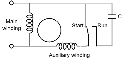
The most common type of starting aid used to start the single-phase induction motor is the starting capacitor connected in series with the auxiliary winding so that the motor can operate as a two-phase machine.
There are different typologies of capacitor motors, each with its own particular characteristics:
– capacitor start motor (that uses the auxiliary winding and capacitor only during starting);
– permanent split-phase capacitor motor (that uses the auxiliary winding and capacitor continuously);
– two-value capacitor motor (one value of capacitance for starting and a different value for running);
– split-phase capacitor motor (that uses the auxiliary winding during starting and running but switches a capacitor into the auxiliary circuit during running only).
Typical applications for the capacitor motors are household appliances, compressors, pumps, fans. These motors are generally available in ratings from as small as 100 W and larger, although special applications may require less than 100 W.
To reduce costs of single-phase induction motor design and fabrication technique, motor manufactures have lost ground in motor efficiency. The recent emphasis on energy consumption demands an improvement of the efficiency of electrical motors and drives. Therefore, it is necessary to develop design procedures for the optimization of the efficiency and cost of single-phase motor designs.
The design of these motors is based on universally accepted physical and mathematical principles which have been verified by the experimental methods. However, with the fast changing technological developments, the knowledge of these principles is often insufficient to find the optimal design.
A specific software has been developed for the optimization of the design of single-phase induction motors. The capacities of the proposed procedure (easiness and flexibility in motor design, reliability of predicted performance) are pointed out considering different objective functions.
The software has been refined on the basis of design and test data of several single-phase induction motors that have been selected by inquiring the main national electrical manufacturers.
The design procedure has been applied to optimize the design of a split-phase capacitor motors, 2-pole, 150 W, 220 V, 50 Hz, commonly used in household appliances.
The optimized designs have been compared with the commercial motor of the same size, in order to evaluate the effective performance improvement.
The mathematical model of the single-phase motor
The single-phase induction motor does not develop any starting torque. In order to generate such a torque an additional auxiliary winding must be provided. Usually, this winding is spatially shifted by 90° with respect to the main phase winding and its current must be time shifted in relation to the current of the main phase winding. Since this auxiliary winding may also improve the properties of the motor at rated speed, it also sometime remains connected for normal operation of the motor.
Because the split-phase starting arrangement allows the use of lower rotor resistance, the split-phase capacitor motor usually operates at a higher efficiency and higher speed than a comparable permanent-split capacitor motor.
A split-phase capacitor motor is represented schematically in Fig. 1.
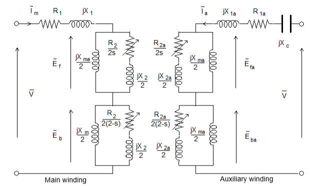
The model of the motor using the well-known “double revolving field theory” is shown in Fig. 2. In this model, the magnetizing reactances Xm and Xma are split between the top and bottom halves of the circuit; R2 and X2 are the rotor resistance and leakage reactance, referred to the stator. The top half represents the motor’s forward rotating component and the bottom half represents the motor’s backward rotating component.
Based on the presented model, a software has been developed to predict the motor performance at different operating conditions. Starting from given motor design data, the parameters of the equivalent circuits are calculated. Since the main and auxiliary phase stator windings consist of concentric coils with non-equal numbers of turns per slot, adequate formulas have been derived for the calculation of the resistance and reactances.
The analysis of single-phase induction motor also includes thermal analysis through a thermal network. It allows to estimate the steady-state temperatures in the stator windings and rotor bars; the motor is divided geometrically into a number of lumped components, each components having a bulk thermal storage and heat generation and interconnections to neighboring components through a linear mesh of thermal impedances.
All performance of the motor (steady-state, no-load, starting operation) are determined through multiloop iterative calculations.
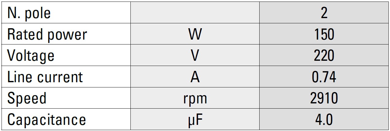
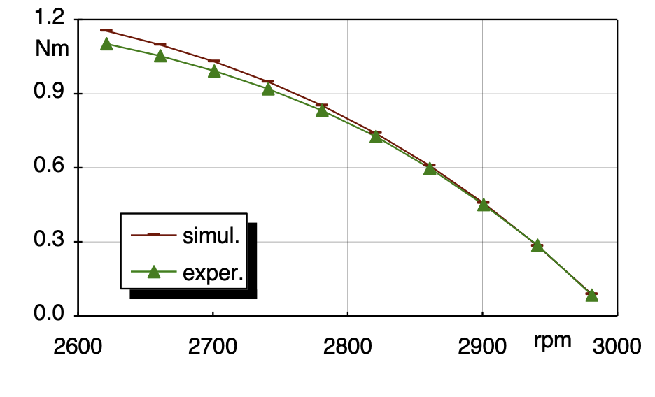
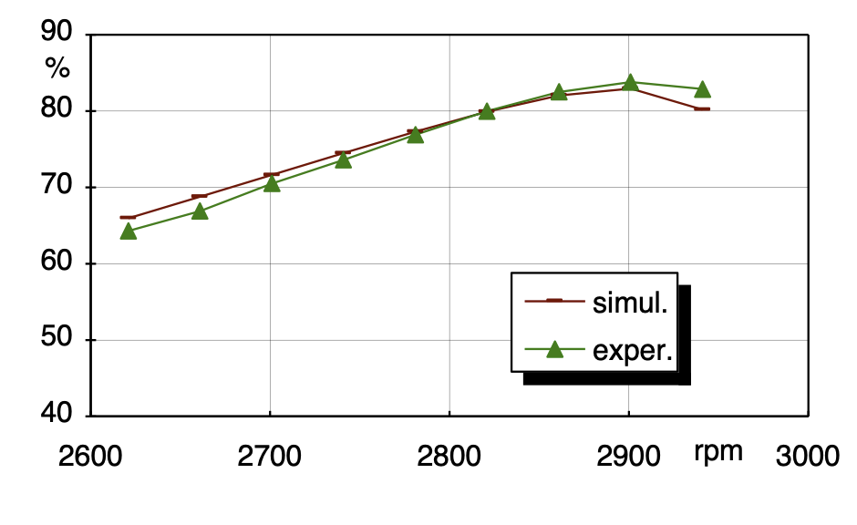
The validity of the mathematical model has been verified by means of experimental tests on a commercial split-phase capacitor motor (which in this study we assume as a reference motor) with the main data listed in Table 1.
TABLE 1 – MAIN DATA OF SINGLE-PHASE INDUCTION MOTOR (REFERENCE MOTOR)
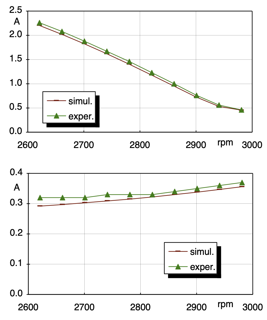
Figures 3, 4 and 5 show the comparisons between the experimental and simulation curves (for the currents, torque and efficiency). These results point out a good agreement between calculations and measurements.
The program is flexible and allows to compute the performance characteristics of the others single-phase induction motors (split-phase, capacitor-start, permanent split-capacitor motor); it is suitable for rated powers in the range between 50 and 300 W.
Design optimization of single-phase induction motor
The optimization of single-phase induction motor design is a complicated task; it usually can be dealt with as a mathematical problem as follows:
find X = (x1, x2, … xn) such that F(X) is a minimum and Gj(X) ≥ 0 for j = 1, 2, … m,
where:
F(X) is the objective function;
X is the set of independent variables;
Gj(X) are the constraint functions;
n is the number of independent variables;
m is the number of constraint functions.
The objective function is the analytic synthesis of the optimization aim and it can be of several types: it is more often of an economical type but nevertheless of a technical one when we want to stress a particular performance.
The constraints are the physical and performance constraints of the design, that is its specifications.
The independent variables concern the stator and rotor shape and stator windings and each variable might be constrained explicitly by upper and/or lower bounds.
The optimization procedure is synthesized in the flow-chart shown in Figure 6. Starting from a “initial design” (or reference motor), the optimization algorithm iteratively updates the set of design variables (X) and try to identify an “optimal” motor by making a trade-off between the different parameters of the machine.
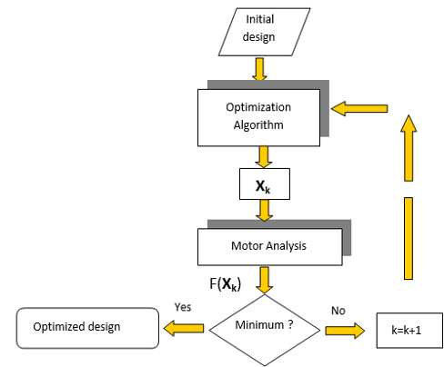
The block “Motor Analysis” evaluates, by the equivalent circuit, the motor performance, the objective function and the constraints values.
This procedure has been used to optimize the single-phase induction motor to be employed in application where a high efficiency or high starting torque are required.
Three different objective functions have been chosen:
OF1) Efficiency;
OF2) Materials cost (iron, copper, aluminium, capacitor);
OF3) Starting torque.
OF1 allows to optimize the motor design without excessive additional cost; in that way the final design will be an optimized motor rather than a derated one. On the contrary OF2 allows an active materials reduction without affecting the motor performance (that are similar to the reference design ones).
The chosen design variables concern the dimensions of the stator and rotor shape, the number of turns and wire sizes of the main and auxiliary winding and the capacitance value of the capacitor.
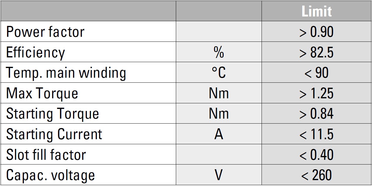
Moreover, several constraints have been assumed and particularly: starting torque, starting current, breakdown torque, power factor, efficiency, stator winding temperature rise, slot fill factor (for the main and auxiliary windings) and capacitor voltage. Table 2 presents the list of constraints and their corresponding limit values.
TABLE 2 – THE CONSTRAINTS
Results and comments
Table 3 presents the performance of the three optimized designs and Table 4 shows the percentage variation of the efficiency, materials cost and starting torque, compared to the reference motor.
TABLE 3 – MOTORS PERFORMANCE
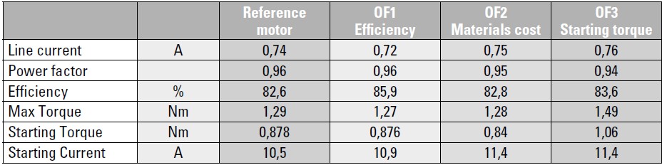
TABLE 4 – PERCENTAGE VARIATIONS COMPARED TO REFERENCE MOTOR
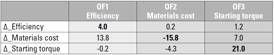
The optimization OF1 presents a general performance improvement with a slight higher material cost (+13.8%) due to the active materials weight and capacitance increasing. The optimization procedure gives rise to a better space exploitation and the final design has the maximum allowable slot fill factor.
The optimization OF2 presents a significant cost reduction of about 16% without affecting the efficiency; in this case the constraint on the starting torque becomes active near the minimum value in consequence of a smaller starting rotor resistance (due to a reduction in rotor slot dimension). This design presents a reduction of the auxiliary and main winding wire sizes; this is to be expected since the cost of copper is high relative to iron or aluminium costs. This reduction is limited from the temperature constraints that are the major obstacle in the cost reduction process of an electrical machines.
The choice of the objective function OF3 gives rise to a final design with higher starting torque (+21%) and a significant efficiency improvement (because of a stator resistance reduction); in this optimization, the active constraint has been the starting current that is close the maximum imposed value.
It is worth mentioned here that the reference commercial motor has been optimized by experienced designers over a period of time and therefore the obtained results are more significant.
Further efficiency improvement can be reached by choosing a suitable semi-processed electrical steel. Simulation results obtained with the proposed optimization procedure and electrical steel with relatively low iron losses have shown an additional efficiency increasing of 2%.
The single-phase motors are widely used in household appliances, and an accurate design can improve the motor performance and efficiency and reduce the consumption of the appliance with savings on the cost of the bill.


